This was the first of three weeks of make a machine assignment. I will be posting my individual contribution on this page, this is a combination of assignment 9 and assignment 11.
We were suppose to work in groups and were asked to come up with a concept of our machine. Neil had asked us to move the parts with hands and test our designs.
Machine concept
My group consists of three members including
Arundhati,she is taking care of the prototyping, eletronics and programming
Deepali, she is doing major designing part and documentation
Me, I am doing procurement of the material, designing and electronics of the machine
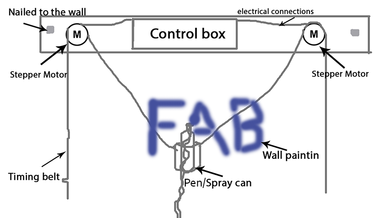
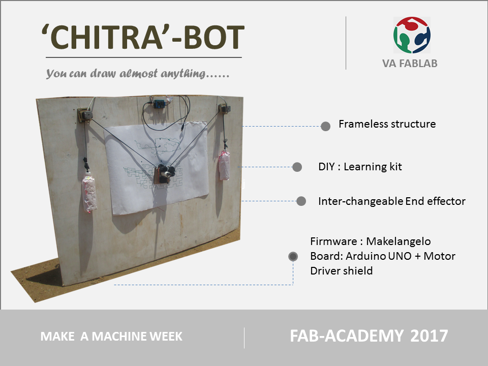
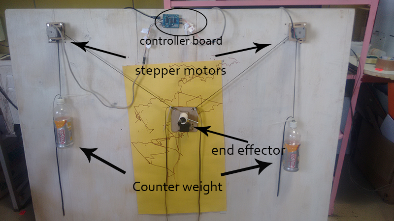
After a detailed discusion with our instructors we set out to make a basic layout of the machine, we decided to make WallBot a machine which will stick to the wall draw using spray can.
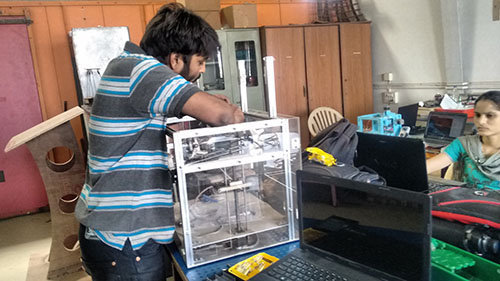
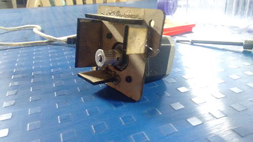
We decided to make a small x y plotter to understand the working of the motor and the belt drive before moving towards the the final design
We planned out the electronics layout, we will be using
2 Stepper motors to make X and Y movement
1 solenoid/ servo motor to actuate the spray can/pen
We would be commercial boards(arduino) in our case, as a lot of documentation is available on the internet about them
12 v power supply
We will also consider using Fabnet board to connect to the nodes and also supply power
2 gesalt nodes to move the motors
12 v power supply for the fabnet board and solenoid
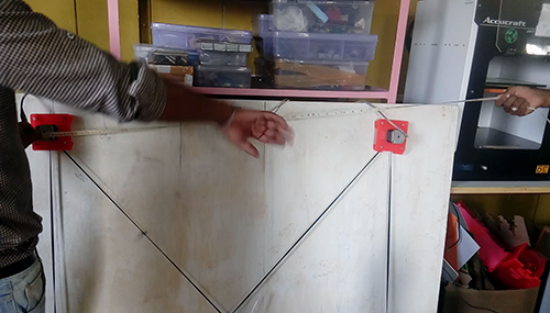
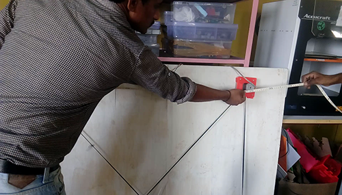
As Neil had asked us to do, we were able to achieve the basic X Y movement with th use of hands.
After making this small machine(which barely works) we realised that our task is going to be daunting, we havent even started with electronics that seems to be the biggest worry
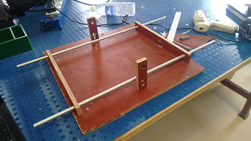
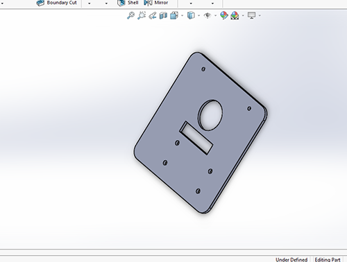
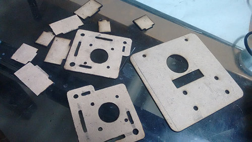
Now we moved to the actual WallBot, we did a basic design of the mounts and penholder
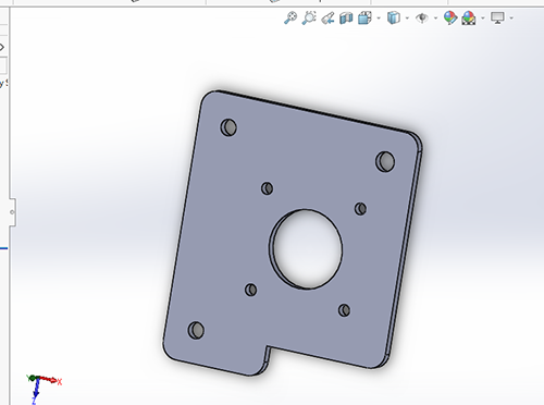
We found a lot of flaws in the machine, the size of the canvas is limited by the number of screws that fix to the motor mount. Thus we modifid the motor mount a bit.
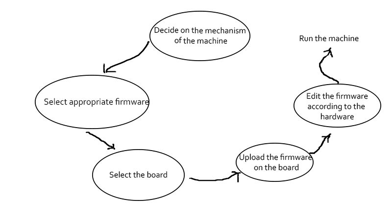
The first part of my job was to decide what mechanism we are going to use for the machine. Our machine has a polar mechanism
Next step was to decide on the firmware and software that we are going to use.
Final step was to edit the firmware according to the hardware of the machine
Trail 1
I started with searching firmwares and compatible boards for the same I found this on the internet
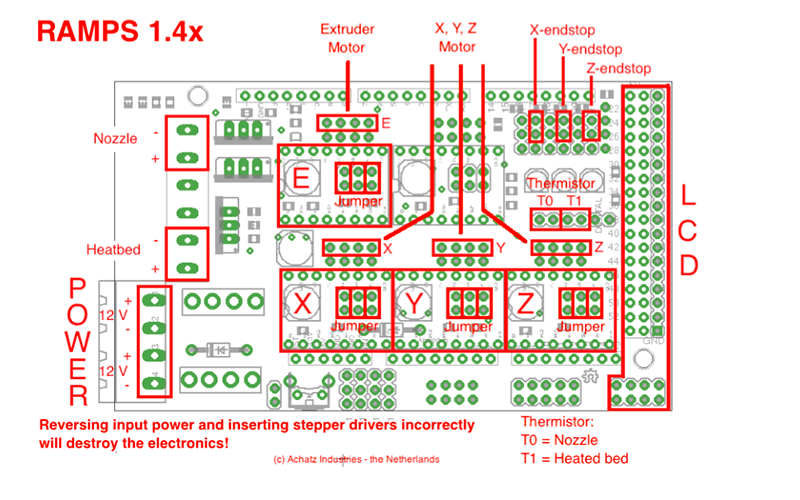
We at viyan Ashram Fab Lab have already tested with Marlin firmware on arduino mega with Ramps 1.4, thus I selected the same combination
As we were going to use arduino(mega/uno) I seleced Marlin firmware
I downloaded the firmware from the above website and used pronterface as a GUI and inkscape plugins to convert my files to gcode
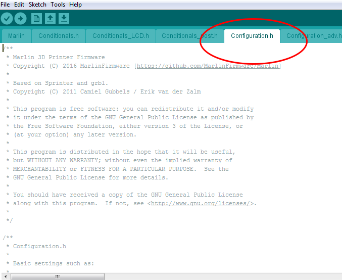
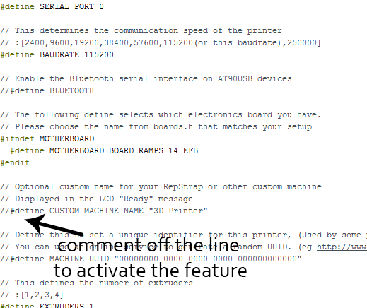
When you download the Marlin Firmware we have several files in our ectracted folder, we open the arduino file and switch to configuration.h file
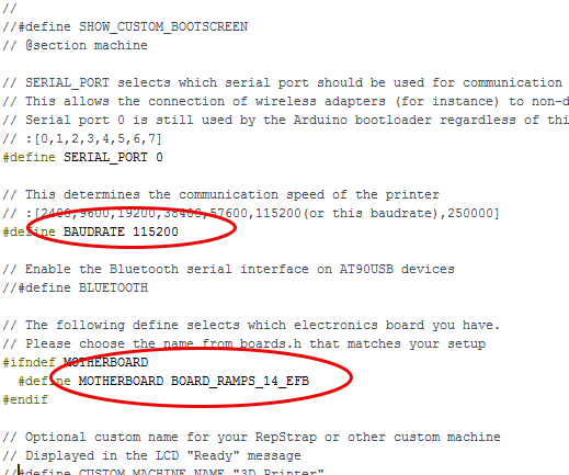
We have to edit the firmware according to our hardware, we have several options to edit such as baudrate,motherboard etc.
We can comment or comment off the features in the firmware that we want
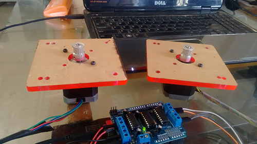
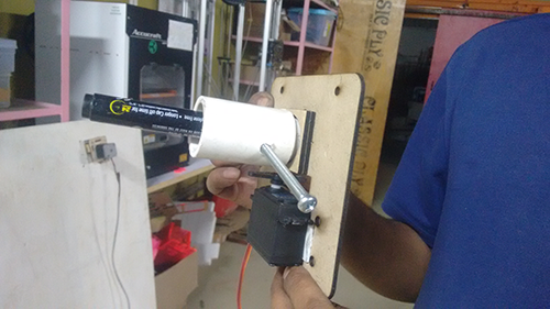
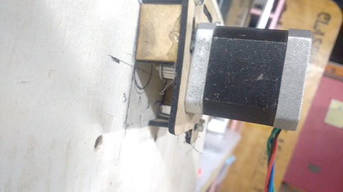
After the firmware was successfully uploaded on the arduino, I connected my motors to the board.
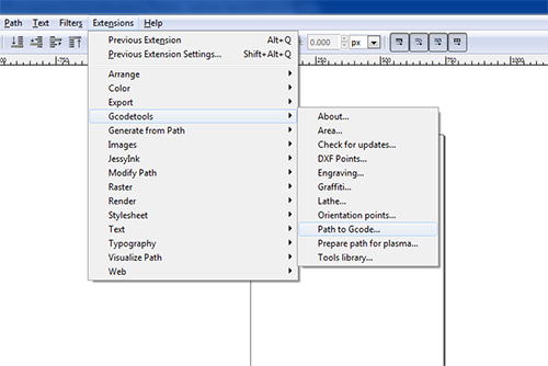
I connected the x and y motors I did not connect the servo as of now, then I got the gcode from inkscape for this we have to download a plugins for inkscape from here
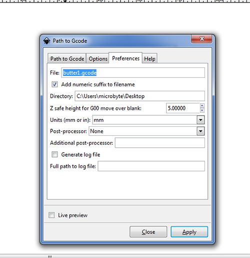
After the plugins are installed we can generate a gcode of the object in inkscape by going to extension option and selecting path to gcode, here we can tweak some options and save the file to the prefered location.
Next we open pronterface and connect the arduino with the pc. After this we select the baudrate and the port and hit connect.
Load the gcode that we did in Inkscape and hit run.
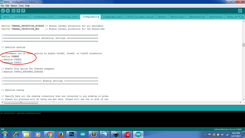
The two motors that I connected starting moving at a very high speed and in a random order, I paused the printing and gave it a direction in X and Y direction seperately but still it behave abrupt, I started digging onto the configuration.h file I realised that the core x y mechanism was commented off this meant that the machine was running a core x y mechanism and thus when I moved the x co-ordinate both motors started moving.
My machine was not using core x y mechanism, I started searching on the internet and found out that Marlin supports Cartesian, Core x y, Delta and Scara mechanism our machine did not have any of these mechanism, ours was a Polar mechanism
Besides Marlin has a lot of features related to heating and temperature which were not anticipated in our machine Thus commenting these features gave a lot of errors while compiling the code
Marlin firmware was specially made for 3d printers and most of the features were not needed in our machine thus I decided to switch away from Marlin
I came across these two polar bots which are on similar lines with the machine we are building PolargrapghSD and Makelengelo
The firmware and the software are available on the git hub website, and I thought of giving it a try.
Trail 2
I started first with PolarBotSD, the docmentation of this particular Bot is very well written, the forums are also very discriptive.
Polargraph is compatible with arduino Mega with Ramps 1.4 which I alrady had, thus I uploadeddownloaded their latest version of the firmware and uploaded it to the board.
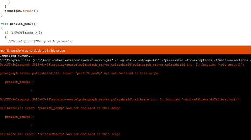
But the firmware of PolargrapghSD wont compile in arduino
This code could be debugged and updated, but we switched to Makelengelo firmware which uploaded without any error on arduino uno. Makengelo is not compatible with arduino mega 2560, thus we shifted to arduino uno
Trail 3
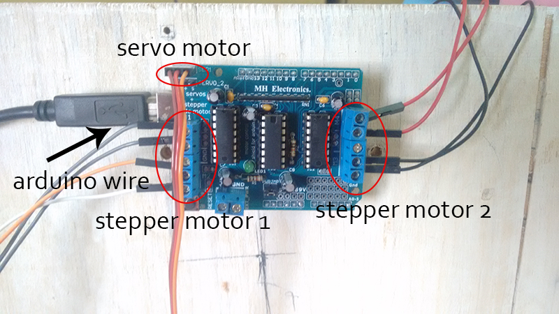
Now that the firmware is uploaded on the board we were ready to make the connections, we are using arduino uno with motor driver shield, the connections are as follows.
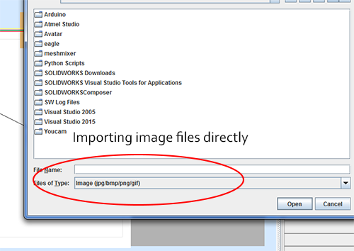
Makelengelo also has its own GUI this is a execuable jar file in the extracted folder, we need to have the latest java installed in our computer to connect our pc to the board, an interesting thing about Makelengelo is that it can convert image files into gcode on its own, thus you dont require to download any plugins for it, you can just import an image the software will convert it into gcode.
We can also import gcode if we have a better gcode converter
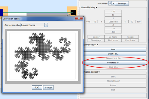
There are also ready to print images in the GUI in the generat art section
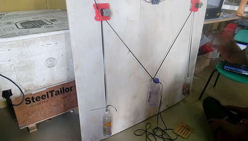
I connnected 12V 1.2amp external power supply to the board, the motor are also using 5v from the arduino board
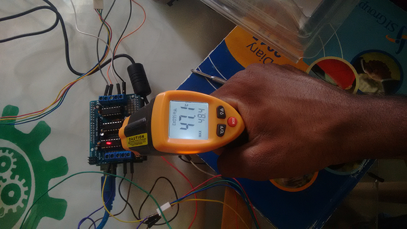
After I connected the power supply the motors are moving fine as I move the X and Y co ordinate of the machine, but the IC on the shield heat up very quickly
Besides the servo motor keeps on moving continuously, this is not recommended as the servo is going to command the position of the pen, it is going to decide when the pen is going to tuch the canvas and when it is slightly lifting awa from the canvas
I disconnected the powersupply and tried running the motors on the arduino power supply itself
I also checked the temperature on an IR temperature sensor this temperature is well within the range
I disconnected the servo motor from the board, and tried running the machine without it.
We go back to solidworks, design our parts and assemble them on a board, this will be our work station and we are going to experiment on this
Scope of improvement
The machine is frameless, in order for it to paint the wall we need to try out vaccum pads
We have to do mechanical calculations such as pulley diameter, steps per revolutions and other things and update them in the firmware for better resolution of the machine.
The servo motor problem still persisits, we need to trouble shoot it in the firmware.
Firmware editting is major scope for improvement, we have to explore every line in the firmware to know its end effect.
Counterweights have to be accurately counted for better gripping of the belt
The motor mounts and the penholder still lag stiffness and strenght, we need to redesign them